

- In this new method of flashing the ESP8266 we have to attach RST & GPIO0 to a pull up resistor R3 and R2 respectively.
- Vcc aand CH_PD is connected to 3.3v directly while GPIO2 is connected to 3.3v through a resistor R4.
- Connect Rx and Tx of esp to Rx and Tx of arduino respectively.
- Now press the Reset button and then press the GPIO0 push button and then release the Reset push button.
- Remember that the GPIO0 push button needs to be held all the time until told to do otherwise.
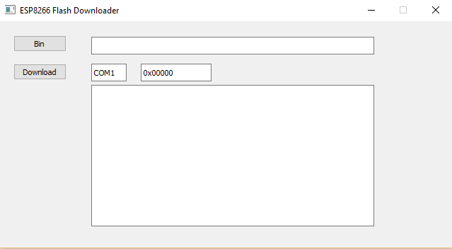
- Now open the ESP8266_flasher and set the correct COM port to which the arduino is connected.
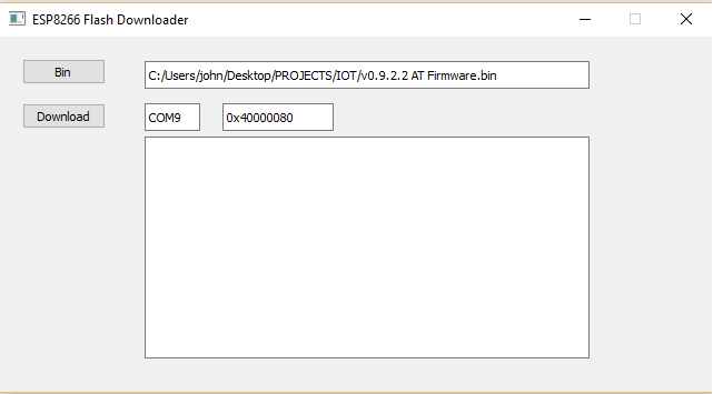
- Now click on Bin and select v0.9.2.2 AT Firmware.
8. Now set the address to 0x40000080 from 0x00000. Now click on download.
 7
7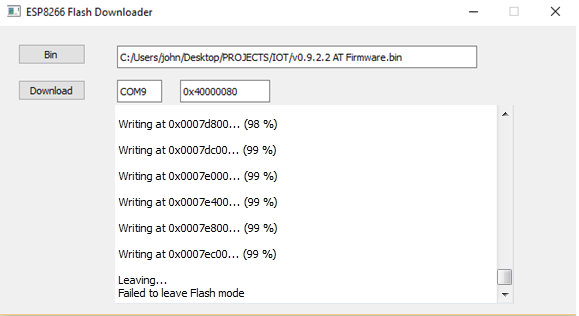
9. After this is done we have updated our esp8266 with this v0.9.2.2 AT Firmware.
10. Now we proceed with checking the AT commands. (Still holding the GPIO0)
AT COMMANDS
|
OUTPUTS
|
AT
|
RETURNS OK
|
AT+CWMODE=3
|
RETURNS OK OR NO CHANGE IF ALREADY SET
|
AT+CWLAP
|
LISTS ALL THE AVAILABLE WIFI IN THE RANGE
|
AT+CWJAP=”WIFI_NAME”,”WIFI_PASS”
|
CONNECTS TO THE WIFI
|
AT+CIFSR
|
RETURNS THE IP ADDRESS OF ESP AND WIFI
|
If all the commands are working as described then we can start with our next step of programming the arduino to send data of sensors to our ThingSpeak server.
No comments:
Post a Comment